Heeeeeelium!
Decay! Decay! Decay!
I had a friend who introduced me to Helium, and I thought
she needed a Helium of her own, so I set about making one.
My objective going in was simply to have some sort of spherical
helium which said "Decay! Decay! Decay!" when it was manipulated in
some fashion. All the more specific design decisions were dictated by
expedience.
 I started out with a very minimalist design for the speaker, involving
a microcontroller and four resistors as a driver. The microcontroller
used was an ATMega8, because I had some in stock, and there was just
enough memory for the sound clip. The resistors were 250, 500, 1k,
and 2k, to form an 8-bit DAC. The values were chosen because 250 ohms
was the smallest value which could be used at 5V without exceeding the
20 mA drive specification of the AVR microcontroller. As it turned
out, I ended up running from 3V instead of 5, and therefore could have
gone a bit lower, but I had already ordered 1% resistors in octave
values starting at 250.
I started out with a very minimalist design for the speaker, involving
a microcontroller and four resistors as a driver. The microcontroller
used was an ATMega8, because I had some in stock, and there was just
enough memory for the sound clip. The resistors were 250, 500, 1k,
and 2k, to form an 8-bit DAC. The values were chosen because 250 ohms
was the smallest value which could be used at 5V without exceeding the
20 mA drive specification of the AVR microcontroller. As it turned
out, I ended up running from 3V instead of 5, and therefore could have
gone a bit lower, but I had already ordered 1% resistors in octave
values starting at 250.
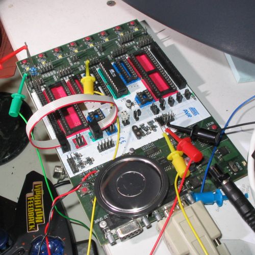
In the picture, you can see the resistors stuffed into the
accessory connector of the STK500 programming board. With just the
resistors, it did work, but it was very quiet. I wanted more volume,
so I added an NPN transistor as an emitter follower, which worked
quite well. I believe I used a pn2222, but it might have been a
2n4401. I don't think it really matters. There's a DC bias on the
speaker, but at this level of quality, that doesn't really matter
either.
Here was the circuit used at this point:
	       __
	    -o|  |o-
	    -o|  |o-
	    -o|A |o-----------------------.
       VCC  -o|T |o-----------------.     |
	+   -o|M |o-----------.     |     |
	|   -o|e |o-----.     |     |     |
	-----o|g |o-    |     |     |     |
	-----o|a |o-    |     |     |     |
	|   -o|8 |o-    |     |     |     |
       ===  -o|  |o-    \     /     \     /     VCC
       GND  -o|  |o-    /2k   \1k   /500  \250   +
	    -o|  |o-    \     /     \     /      |
	    -o|  |o-    /     \     /     \      |
	    -o|__|o-    |     |     |     |    |/
			-----------------------|
					       |>
						 |  __ /|
						 ^-|  | |
						 .-|__| |
						 |     \|
						===
						GND
 I had originally intended to use some sort of tilt switch, probably
and old scrounged mercury one, for activation. Unfortunately, I
couldn't find any old ones, and by the time I realized that, I didn't
have time to order one anymore. Thus, I modified the design and ended
up using a magnet in a tube with a reed switch. This part didn't go
particularly well. I destroyed two or three reed switches bending the
leads, and the positioning of the magnet enclosure such that it was
close enough to activate the reed switch, yet not so close that it
would get stuck, turned out to be extremely difficult. Since I don't
recommend the sensing method I used, I won't go into detail about the
construction of it.
I had originally intended to use some sort of tilt switch, probably
and old scrounged mercury one, for activation. Unfortunately, I
couldn't find any old ones, and by the time I realized that, I didn't
have time to order one anymore. Thus, I modified the design and ended
up using a magnet in a tube with a reed switch. This part didn't go
particularly well. I destroyed two or three reed switches bending the
leads, and the positioning of the magnet enclosure such that it was
close enough to activate the reed switch, yet not so close that it
would get stuck, turned out to be extremely difficult. Since I don't
recommend the sensing method I used, I won't go into detail about the
construction of it.
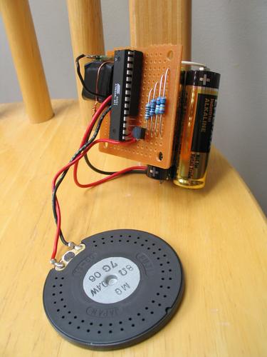
The figure to the right shows the assembled circuit. It's powered
from 2 AA alkaline batteries. Note the other kwality features, like
the socket which is the wrong size because I didn't have any correct
ones in stock.
To get the actual data for the music, I captured some audio from
the flash animations on the web site, and then converted it into 8-bit
raw format at 11kHz with Sox.
The final conversion to four-bit audio in was performed with a Perl
script. The following link contains the actual code I used. The
audio data I used is not included, since I could conceivably be sued
for copyright infringement if I distributed that, but the Perl scripts
used to generate it are included, so you can put in your own from
whatever source you want. Note that the pin assignments changed
between the preliminary circuit diagram above (which was set up to use
a convenient part of the expansion connector on the programming board)
and the actual board, so don't wire it up as shown above and then use
the code unmodified.
AVR Code, including one-liner converstion scripts
 I left the "artistic" part for last. I started with a styrofoam
sphere from a local craft supply store, and then cut out two arms from
smaller blocks of the same styrofoam and attached them with wire. The
entire thing was then given a coat of pink acrylic, which took nearly
a day to dry. The red, white, and black details were added once the
pink was dry.
I left the "artistic" part for last. I started with a styrofoam
sphere from a local craft supply store, and then cut out two arms from
smaller blocks of the same styrofoam and attached them with wire. The
entire thing was then given a coat of pink acrylic, which took nearly
a day to dry. The red, white, and black details were added once the
pink was dry.
There's a cutout in the back where I inserted the circuit. I had
originally intended to cover up the hole with a piece of paper or felt
or something prior to painting it, but then I realized that the
intended audience was probably going to rip it out anyway to see how
it worked, so I ended up leaving it exposed.