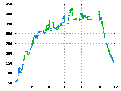
I moved on from that to roasting in a cooking pot with a heat gun. My heat gun eventually stopped heating, and I bought a more expensive heat gun with continuously variable heat and a filter on the air intake. However, I eventually had the bright idea of putting a thermocouple in the pot, and measuring the temperature over time. The result, shown to the right, was not very even. I wasn't sure whether this was because the heating itself was uneven, or because the measurement was unreliable, but I suspected the former.
The last straw was a test I did to investigate the effects of roast profile. I roasted the same coffee twice, to the same final color and time after first crack, but once I took 3 minutes and the other time I took 15 minutes. The difference in taste was extreme - if I had not roasted it myself, I would not have believed it was the same coffee.
This would not do. A repeatable, controllable roaster was needed.
I knew from previous experience that in order to get enough heat out of the Poppery II, it would be necessary to reduce the fan speed. My initial plan was to have a switch to set the fan on low (for roasting) and full (for cooling). I would then control the heating coil with a relay. This plan fell apart in preliminary testing, when I concluded that the relay could not switch the heater fast enough. I measured how quickly the temperature in the chamber rose and fell when the heater was connected and disconnected, and there was a change of tens of degrees within a second. A mechanical relay could not be expected to survive switching multiple times within a second for long, and switching more slowly would have resulted in unacceptable variations in air temperature.
With the mechanical relay unsuitable, there was no remaining hope of completing the project with only parts on hand. Since I was going to have to order parts anyway, I decided to get everything I might want.
I opened up the popcorn popper. I disabled its internal thermostat,
and also disconnected the heaters and brought out their leads to be
connected externally. I decided to switch them on the neutral side,
primarily because I thought this would reduce my chances of shocking
myself while working with them. I also brought out a lead from live
to power the 5V supply. I brought all the wires out one of the small
ventilation holes near the bottom of the case. There already exist
excellent web pages on what you will find in a Poppery II, so I shall
not attempt to duplicate them here.
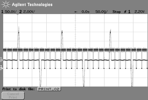
The solid state relays are interesting because they switch only on zero crossings. Upon my first examination of the solid state relay behavior when driven with a signal generator, I saw that they aliased when driven at frequency comparable to or above 120 Hz. I decided to take advantage of this behavior instead of avoiding it - if the duty cycle of the solid state relay is 1/3, and the frequency is high, then one out of three half-cycles will be energized, and without my needing to somehow synchronize the PWM command with line frequency. Perfect!
The solid-state relays also require heat sinks, and list a maximum operating temperature of 100°C. I had purchased some small heat sinks which mounted perfectly on the solid state relays. Unfortunately, in the case of the heater, this heat sink proved inadequate. In a worst-case test with rapid switching and a high duty cycle, I measured a temperature of 95°C and still rising when I terminated the test. I therefore got an old computer heat sink out of the junk parts bin, and drilled and tapped a mounting hole in it. For the fan control, switching <2 A, the original small heat sink was perfectly adequate.
The thermocouple wires proved to be completely unsolderable, so I had to use the screw connections in the original plug. This put the connection further away from the AD595, which is a possible source of error, as the cold-junction compensation will be incorrect if chip is not at the same temperature as the actual cold junction. However, I have observed no significant problems so far.
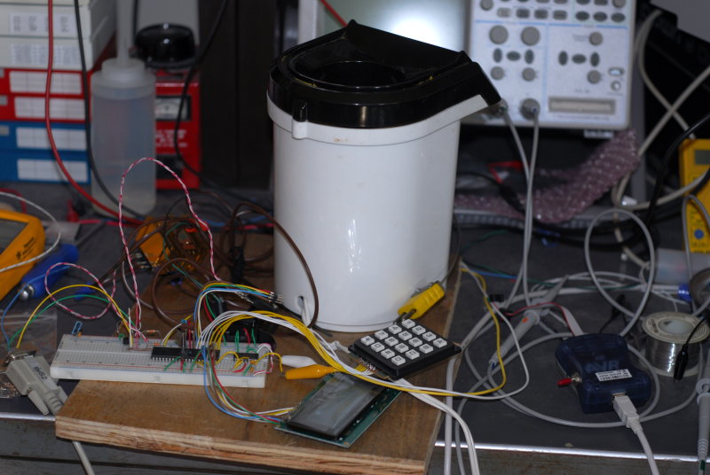
I initially connected all the electronic components on a solderless breadboard while I debugged the connections from the microcontroller to the temperature sensor, LCD, and keypad. The picture to the right shows the roaster in a preliminary state on my workbench.
The first order of business was getting the LCD working, because without a display, it's hard to debug anything else. Unfortunately, getting the LCD working involved some quality time with the logic analyzer mode of my oscilloscope, but all the mistakes were mine and there were no fundamental problems.
Once all the components were connected, the first mode implemented was manual control, where the keypad was used to increase and decrease the duty cycle of the fan and heater. I roasted several batches of coffee in this state, and the most difficult part was getting the coffee out again - it turns out to be somewhat difficult to turn a piece of plywood with a half-dozen components loosely sitting on it upside down.
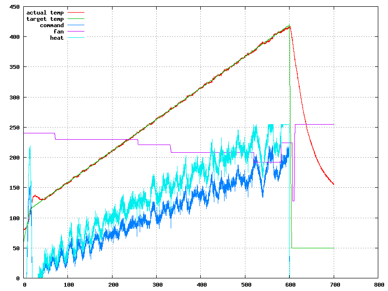
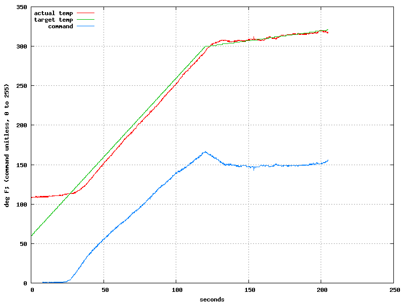
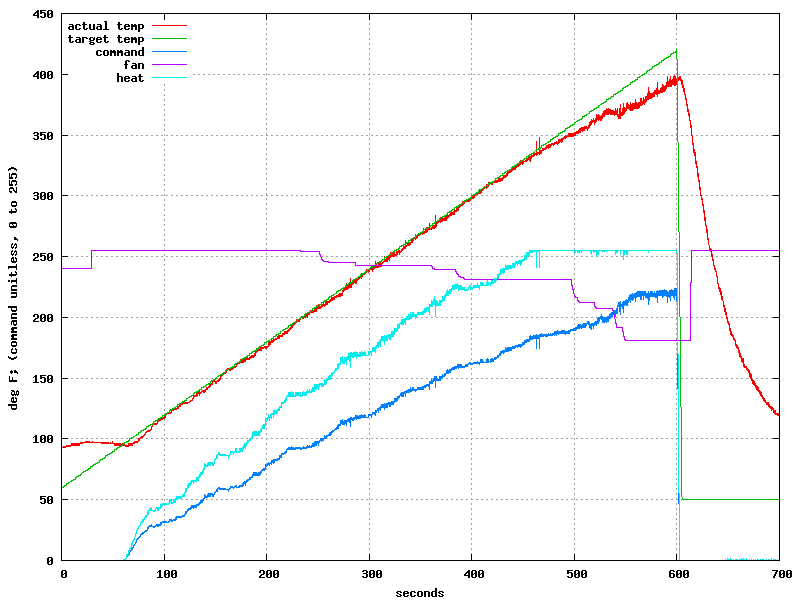
I wanted more than manual control; I did not build a system with a microcontroller so that I could turn the heat up and down myself. My first attempt was to use an LQR controller, but after a day of reading Stengel and looking online, I ultimately struck out at implementing one. I therefore fell back to using a PI controller. The PI controller has only one output, but I need to control both the fan and the heat. I decided to leave the fan under manual control, and use open-loop control (i.e., a calculation) to adjust the heater command given the fan setting. I did a series of tests to check how fan setting affected the actual temperature (raising the fan 50% lowered the temperature 20%), and used this to adjust the command coming from the PI controller to compensate for the fan setting in effect. (In some of the graphs, "command" is before this compensation, and "heat" is after).
This worked out quite well, with the feedback in the outer loop adequate to compensate for any errors in the fan compensation. I tuned the controller parameters by hand, and initially I had the gains much too high, resulting in high-frequency noise from the P gain and oscillation from the I gain. I subsequently tuned them better.
The temperature profile is straightforward - it is limited to being piecewise linear at this time, and one uses the LCD to enter time and temperature points. The EEPROM provides enough space to store four programs of up to 32 points each, and could be increassed with compression or more intelligent packing.

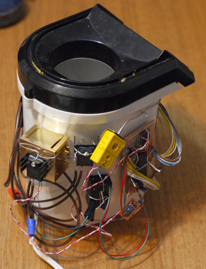 The roaster in its "assembled" form is shown to the right, with all
the components attached to the outside of the housing with stainless
safety wire. There are only a few exposed 120v connections, and
nothing falls off when I turn it upside-down to get the coffee out, so
I'm calling it done.
The roaster in its "assembled" form is shown to the right, with all
the components attached to the outside of the housing with stainless
safety wire. There are only a few exposed 120v connections, and
nothing falls off when I turn it upside-down to get the coffee out, so
I'm calling it done.
The roaster has had some problems achieving the desired temperatures under unfavorable conditions - in one case, I was outside in freezing weather, and had a 150g batch, and it could not achieve the desired temperature ramp at the end, with the heater running at 100% duty cycle. I think this can be worked around by operating inside with an exhaust fan, with warmer intake air, using <100g, or by using profiles with a slower ramp at higher temperatures. I've never heard of anyone else using a linear ramp for coffee, and I use it only because it was an obvious starting point, not because I think it has any actual advantages.
I am extremely happy with the results. I think this roaster gives me everything I need to investigate the effects of roasting profile on the taste of coffee. I may make some minor improvements to the profile control UI, or implement curves instead of only linear interpolation, but I expect that most of my future energy will go into actually roasting coffee, tasting it, and adjusting the profile.
If you are working on a similar project, I would be happy to share the AVR source code, which is a mix of C and assembly. Of course, if you are local, I would also be happy to share some delicious freshly-roasted coffee.